Structural Design of Air Powered VTOL Lander
Introduction:
The ASTRA v2 air-powered VTOL lander was developed as a reusable guidance, navigation, and control (GNC) test platform capable of validating autonomous vertical takeoff and landing technologies while remaining simple, affordable, and rapidly repairable. Key system requirements included the use of air-breathing propulsion, a minimum thrust-to-weight ratio of 1.1, a flight endurance of at least 90 seconds, full six-degree-of-freedom control through a single thrust source, and the ability to perform multiple flights with only battery replacement between missions. The vehicle was also required to withstand wind disturbances, integrate with a safety tether system, and support rapid transportation and maintenance. Three primary flight profiles were established to demonstrate increasing levels of capability: an air-landing maneuver involving a controlled descent from a 2 m altitude and velocity nulling prior to touchdown, a hover mission requiring the vehicle to ascend to 2 m and remain within a 1 m cube for 30 seconds, and a divert hop that combined vertical ascent with a 2 m lateral translation before landing within a 1 m diameter target area. These profiles were selected to progressively validate vertical control, hovering performance, and horizontal maneuvering while remaining suitable for indoor testing and minimizing ground effect influences.
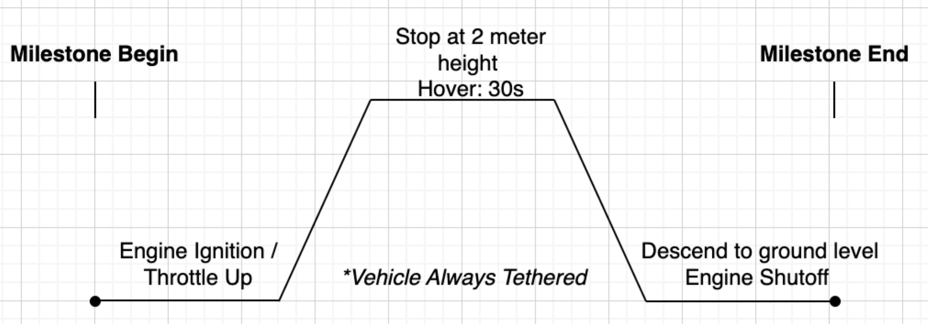
Hop mission profile
General Structural Layout of the Vehicle
The overall ASTRA v2 structure was organized around three major subsystems: the avionics bay, the gimbaled propulsion system, and the landing system. A lightweight modular frame constructed from four continuous 5 mm diameter carbon-fiber rods serves as the primary load path and mounting interface for all subsystems. The vehicle has an overall height of approximately 29.2 inches, a frame diameter of 3.23 inches, and a landing footprint of approximately 25 inches. This architecture was chosen to minimize structural mass while maintaining sufficient rigidity for flight operations and landing loads. All subsystem mounts interface directly with the carbon-fiber frame through standardized set-screw connections and heat-set threaded inserts, allowing individual modules to be removed, repaired, or upgraded without redesigning the entire vehicle. The resulting structure provides a lightweight yet robust platform capable of supporting the propulsion, avionics, and landing systems while maintaining a low overall mass and a compact packaging arrangement.
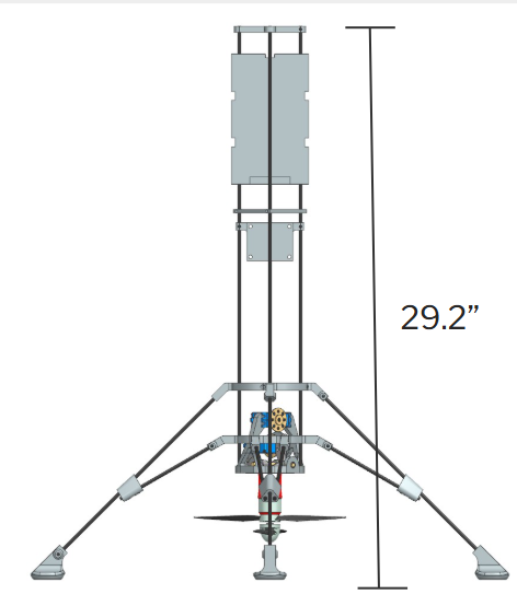
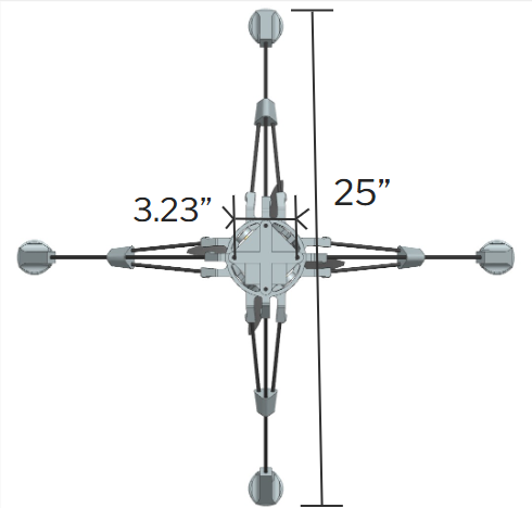
Vehicle dimensions
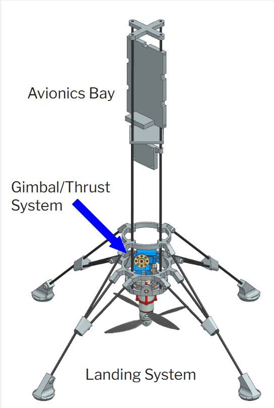
Full assembly
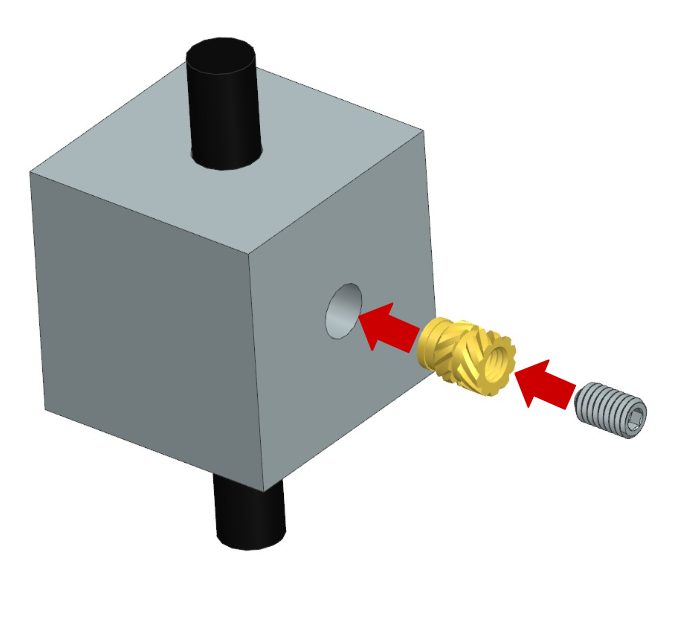
Set screw method for component interfacing
Gimbal Design
Attitude control for ASTRA v2 is achieved through a fully gimbaled propeller system that vectors the entire propulsion assembly rather than relying on aerodynamic control surfaces. The gimbal was designed to provide ±10 degrees of thrust vector deflection about two axes while remaining compact enough to fit within the limited space available beneath the vehicle. The system consists of concentric gimbal rings supported by bearings and driven through dual servo-actuated four-bar linkages. Rotation commands are transmitted from the servos through the linkage mechanism, allowing the thrust vector to be redirected rapidly and precisely. The design utilizes a combination of 3D-printed components and laser-cut structural elements to reduce manufacturing complexity and cost while maintaining sufficient strength. The gimbaled propulsion approach was ultimately selected because it most closely replicates the thrust-vector-control architecture intended for future liquid-fueled lander projects, provides high flight endurance, and avoids the aerodynamic losses associated with thrust vanes or stator systems.
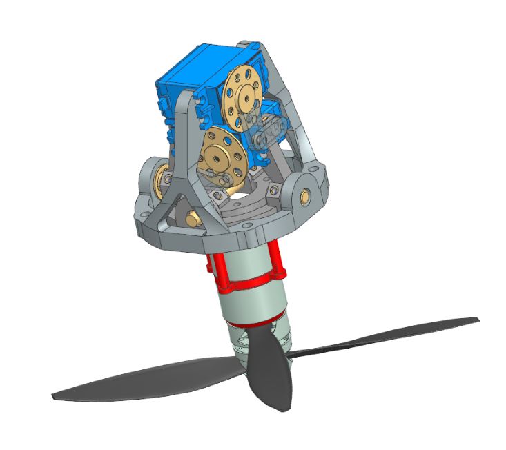
Gimbal sub-assembly
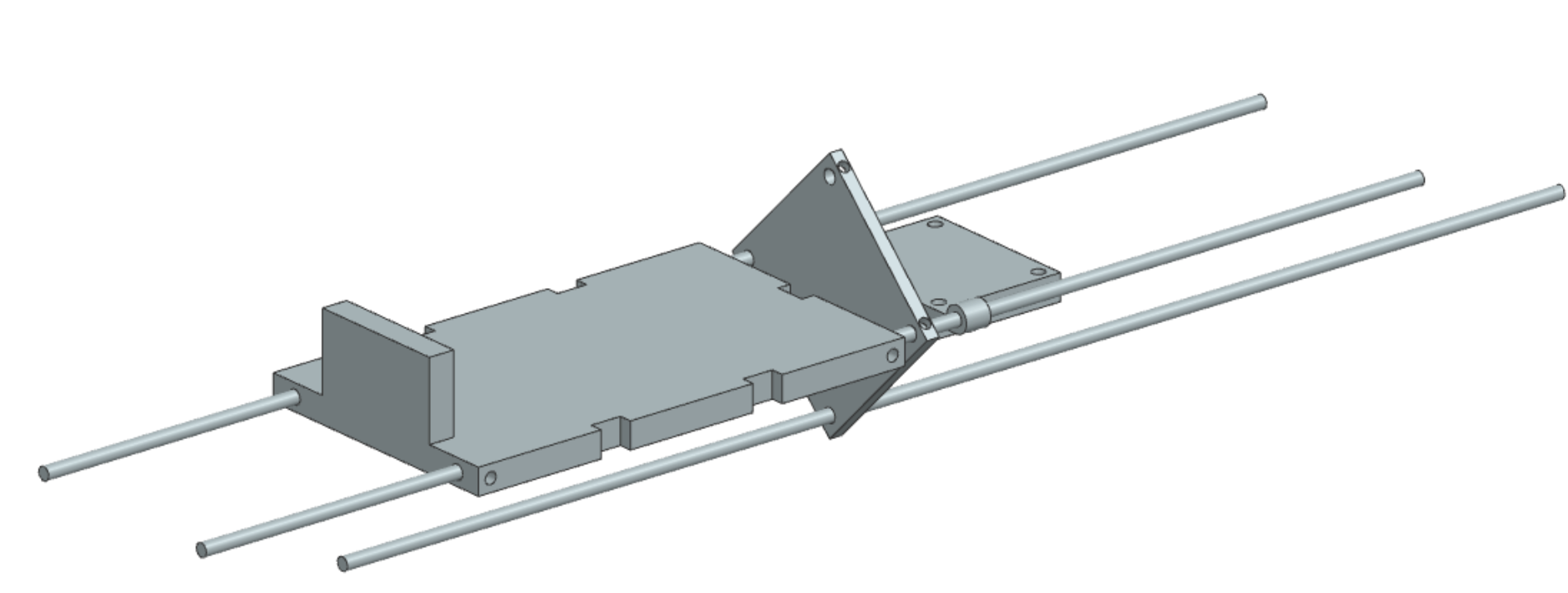
Avionics Bay Design
The avionics bay was designed to securely house the vehicle's flight computer, battery, and electronic speed controller while integrating seamlessly with the modular frame architecture. The primary structural element of the bay is a vertically mounted backplate that supports the battery and transfers loads directly into the carbon-fiber frame. The battery is retained using a combination of a support lip and zip-tie restraints, providing a lightweight and easily serviceable mounting solution. A separate flight computer plate is positioned near the center of the vehicle to minimize inertial effects and improve sensor measurements by locating the avionics close to the vehicle's center of gravity. The electronic speed controller is mounted on a dedicated plate designed to maximize airflow and thermal dissipation while avoiding the need for an enclosed housing. All avionics components attach to the standardized carbon-fiber rod framework using common mounting interfaces, allowing components to be easily removed for maintenance, upgrades, or troubleshooting. This modular arrangement improves accessibility, simplifies assembly, and ensures that electronic systems can withstand the dynamic loads experienced during flight and landing operations.
Landing leg sub-assembly concept
Landing Leg and Frame Design
The landing system was designed to provide a stable, reusable, and lightweight platform capable of surviving repeated vertical landings without the use of sacrificial or crushable components. Following a trade study between inverted tripod and cantilever configurations, a four-leg cantilever design was selected to maximize ground clearance for the gimbaled propeller while maintaining stability during touchdown. Four landing legs were chosen as the optimal balance between stability and mass efficiency while also providing geometric symmetry with the vehicle's two-axis gimbal system. Each leg is constructed using carbon-fiber rods connected through 3D-printed structural joints and rigid attachment points integrated into the main frame. The overall landing footprint spans approximately 642 mm, providing a broad base to resist tip-over during landing operations. Curved foot geometries were incorporated to help the vehicle self-right following slightly off-nominal touchdowns, while fixed structural rings and reinforced connection points distribute landing loads throughout the frame. Together, the carbon-fiber frame and cantilever landing system create a lightweight yet durable structure capable of supporting the vehicle during both nominal operations and minor off-nominal landing events.
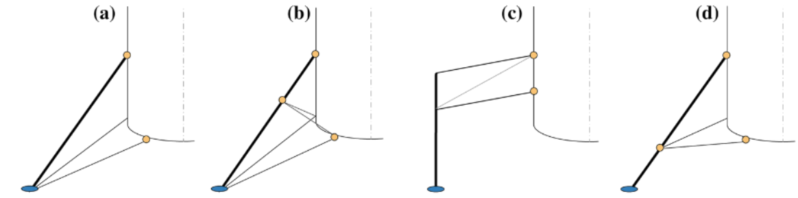
Landing leg designs that were considered
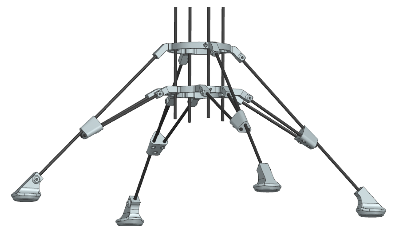
Landing leg sub-assembly