Aircraft - Design, Build, Fly
Introduction:
The objective of this project was to design, build, and flight test a fixed-wing radio-controlled aircraft capable of successfully completing the Purdue AAE 451 Design-Build-Fly mission. The aircraft was required to fit within a storage volume of 75 cm × 75 cm × 150 cm, maintain a maximum takeoff weight below 6 kg, take off within 25 m, climb to 30 m altitude, complete three laps of the flight course, and land without sustaining damage. Additional requirements included carrying at least one payload cube, operating with less than 1000 W of electrical power, providing rapid assembly and payload installation, and maintaining stable flight characteristics both with and without payload. The design effort focused on maximizing low-speed performance and payload capability while ensuring manufacturability, structural integrity, and compliance with all mission requirements.
Design Process:
Weight Estimation and Constraint Analysis
The preliminary design process began with the development of a weight estimation diagram and aircraft constraint analysis to establish a feasible design space. A top-down weight estimation was performed using historical aircraft data and subsystem mass projections to predict the aircraft's maximum takeoff weight, resulting in an estimated design weight of approximately 3.87 kg. This estimated weight served as a key input to the aerodynamic and performance analyses that followed. Simultaneously, a wing loading versus power loading constraint diagram was generated using performance requirements associated with stall speed, takeoff distance, climb performance, cruise flight, and turning maneuvers. Each mission requirement produced a separate constraint boundary, and the overlapping feasible region defined the combinations of wing loading and power loading capable of satisfying all competition requirements. The selected design point was chosen from within this feasible region to provide adequate performance margin while minimizing aircraft size and power consumption. Together, the weight estimation diagram and constraint analysis established the foundation for the subsequent aerodynamic sizing, propulsion selection, and overall aircraft configuration development.
Concept Generation and Selection
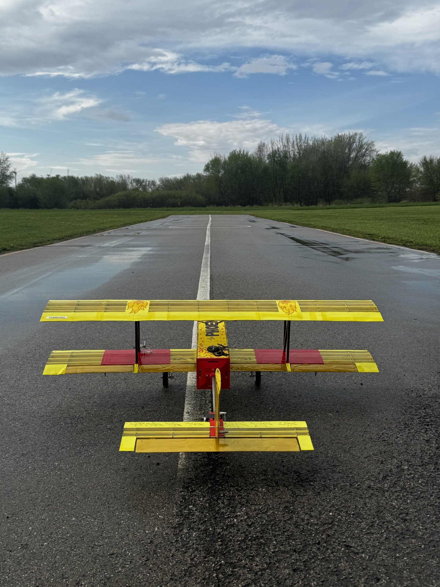
Multiple aircraft configurations were generated using a morphological chart that examined combinations of wing arrangements, tail configurations, fuselage layouts, landing gear concepts, and propulsion architectures. Five complete concepts were developed and evaluated using a weighted decision matrix that considered low-speed stability, cost, manufacturability, short takeoff performance, maneuverability, and landing performance. The biplane configuration achieved the highest overall score due to its superior low-speed lift characteristics, excellent short-field takeoff capability, robust landing behavior, and inherent stability. Although the configuration introduced additional manufacturing complexity and structural weight, these tradeoffs were considered acceptable given the mission emphasis on low-speed flight performance and payload carrying capability.
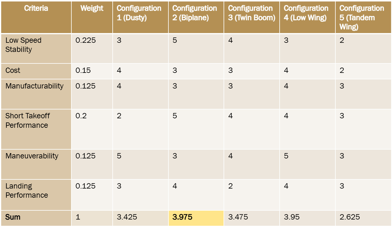
Weighted decision matrix
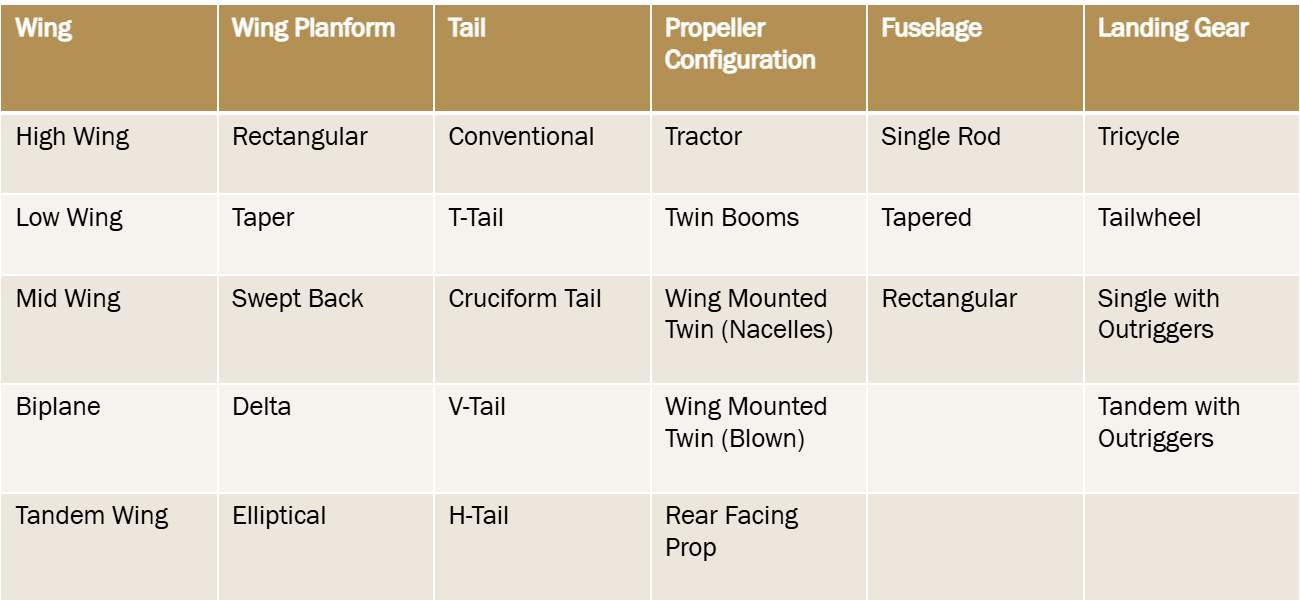
Morphological chart used to generate possible aircraft comcinations
Wing Selection and Sizing
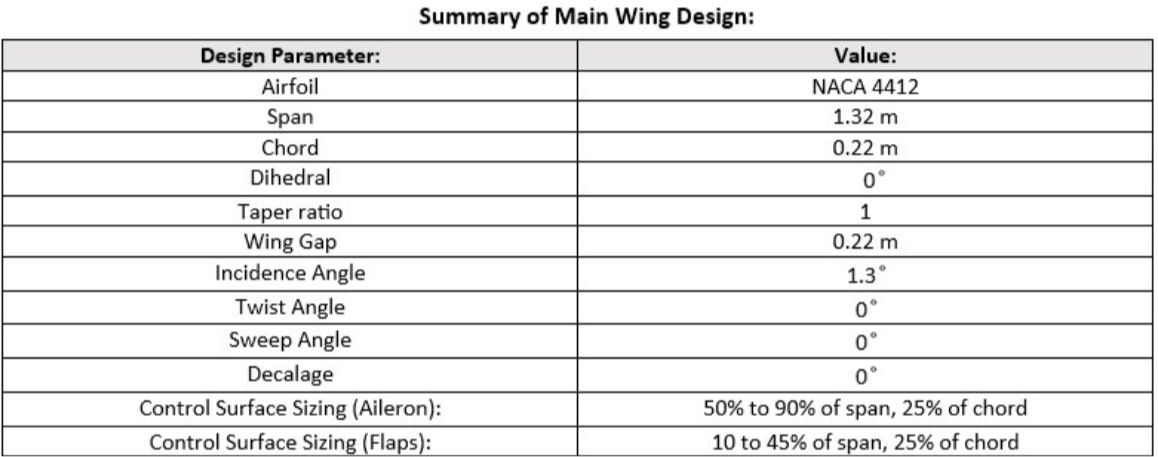
Following configuration selection, detailed aerodynamic sizing was performed. A trade study compared candidate airfoils, ultimately resulting in the selection of the NACA 4412 airfoil for both wings due to its favorable lift characteristics within the aircraft's anticipated Reynolds number range. Wing sizing was based on the wing loading determined during the constraint analysis, resulting in a total reference area of approximately 0.58 m² and a span of approximately 1.34 m. A rectangular planform was selected to simplify manufacturing while maintaining predictable aerodynamic performance. The biplane arrangement allowed the aircraft to achieve a large effective lifting area within the dimensional constraints imposed by the competition, significantly improving takeoff and climb performance.
Static Margin and Center of Gravity Selection
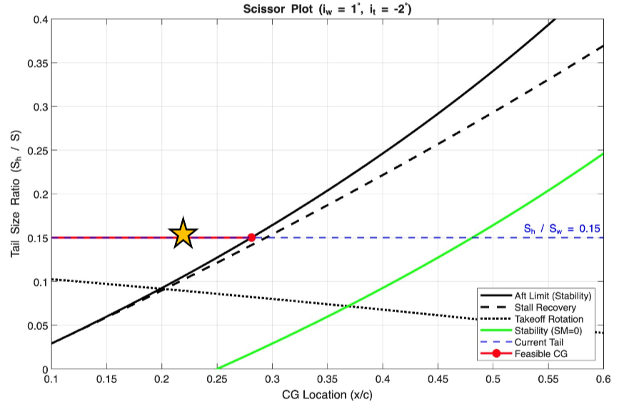
Longitudinal stability was evaluated using a scissor plot methodology to establish an appropriate center of gravity location and tail sizing. The design objective was to achieve a minimum static margin of 20% while maintaining adequate controllability throughout the mission. Analysis resulted in a selected center of gravity location at 22% of the main wing chord. With the aircraft neutral point located at approximately 48% chord, the resulting static margin was calculated to be 26%, providing a comfortable stability margin while maintaining responsive handling characteristics. This balance between stability and controllability was critical for ensuring successful operation both with and without payload.
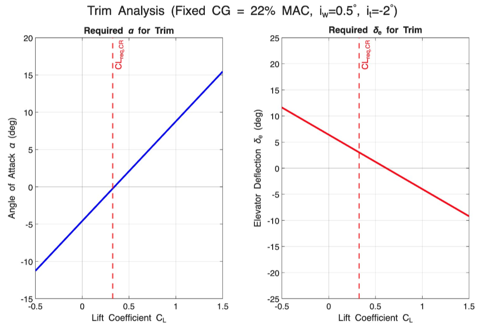
Trimming Envelope Analysis
Aircraft trim characteristics were evaluated to determine the angle of attack and control surface deflections required for steady flight. Using aerodynamic force and moment balance equations, the required lift coefficient at cruise conditions was calculated to be approximately 0.326. The trim analysis predicted a trimmed angle of attack of approximately -0.23 degrees and a corresponding elevator deflection of approximately 3 degrees. Elevator effectiveness was estimated using thin-airfoil theory, allowing the team to verify that sufficient control authority existed throughout the expected flight envelope.
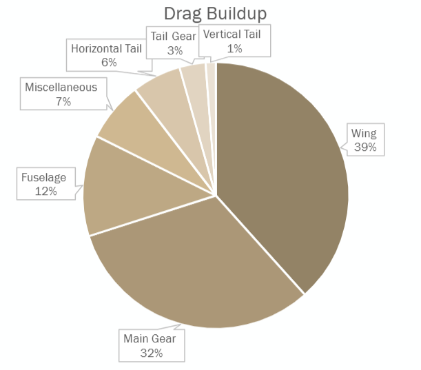
Drag Buildup Analysis
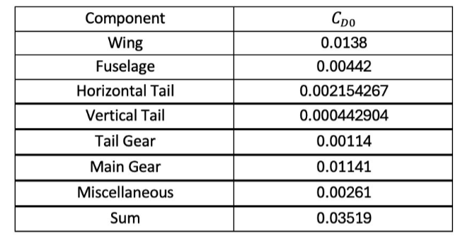
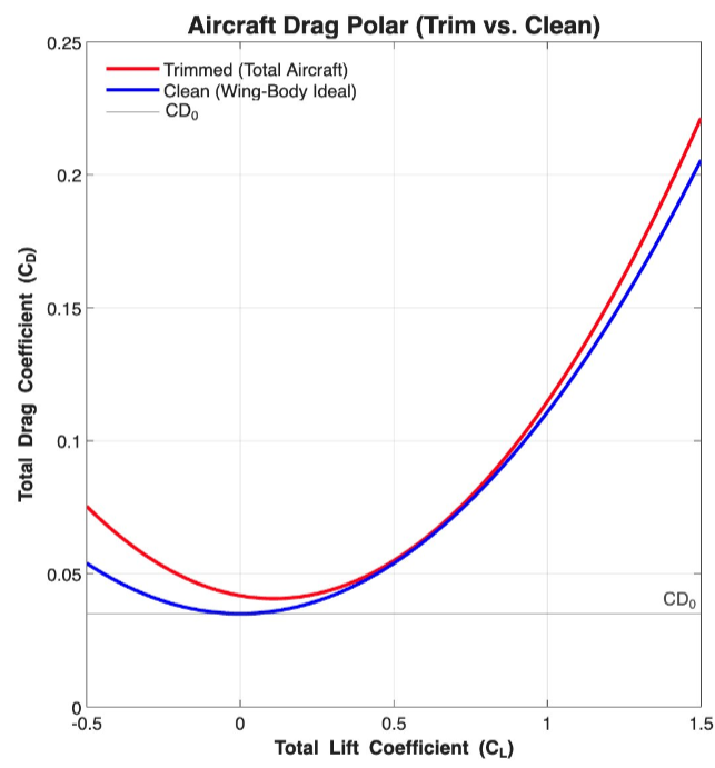
A comprehensive drag buildup analysis was conducted by calculating the drag contribution of each major aircraft component. Contributions from the wings, fuselage, horizontal tail, vertical tail, landing gear, and miscellaneous sources were estimated using analytical methods. Results showed that the wings accounted for approximately 39% of the total drag while the main landing gear contributed approximately 32%, making these the dominant sources of aerodynamic resistance. The resulting drag polar was used to estimate aircraft performance, determine cruise requirements, and assess the drag penalties associated with maintaining trimmed flight conditions.
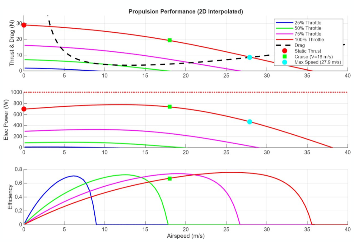
Propulsion System Selection
The propulsion system was selected through a combination of performance analysis and component trade studies. Aircraft performance calculations indicated a required electrical power of approximately 735 W and a minimum static thrust requirement of 17.05 N. A Cobra C-3525/12 brushless motor paired with an APC 11×10E propeller was selected because it provided approximately 760 W of input power and over 20 N of static thrust, exceeding all performance requirements. Battery sizing was based on current draw, flight duration, voltage requirements, and discharge capability. While the original design called for a Turnigy 3000 mAh 5S battery, supply constraints required substitution with an HRB 3600 mAh 5S battery that still satisfied all mission requirements. An Aerostar 60 A ESC was selected to safely handle the motor current while providing adequate margin for transient operating conditions.
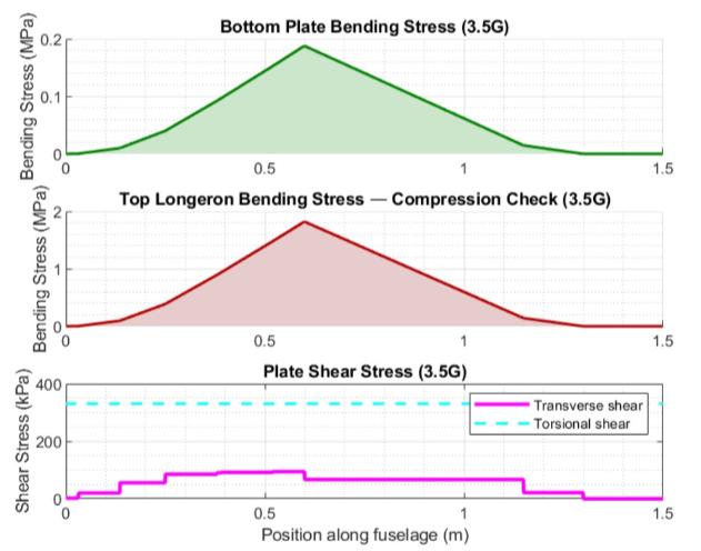
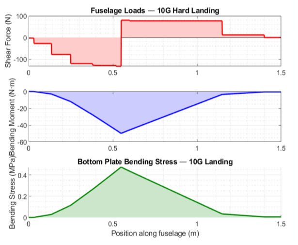
Structural Design
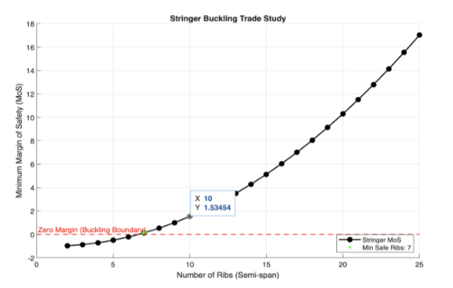
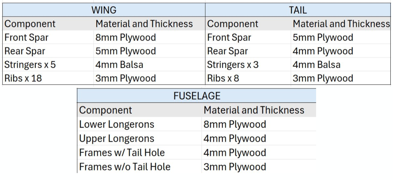
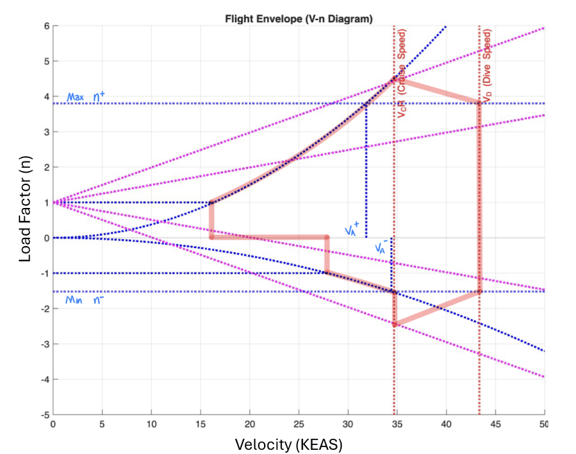
The structural design process began with the creation of a V-N diagram to establish the critical flight loads that the airframe would experience. Analysis predicted a maximum positive load factor of 4.4 and a minimum load factor of -1.52, establishing the design conditions for subsequent structural calculations. Wingbox load analyses were then conducted for both the upper and lower wings to determine spar sizing and internal reinforcement requirements. Several spar configurations were evaluated using calculated bending and shear stresses, resulting in the selection of an arrangement that provided an adequate margin of safety while minimizing weight. Tail structures were similarly sized to withstand aerodynamic loading, while fuselage loading analyses were used to design the internal frame and longeron structure. The final airframe employed a lightweight wood construction featuring plywood ribs, spars, longerons, and bulkheads that provided sufficient strength while maintaining a low overall structural weight.
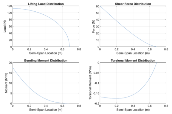
Lower wing load analysis:
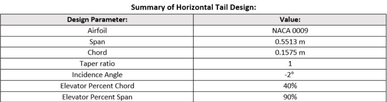
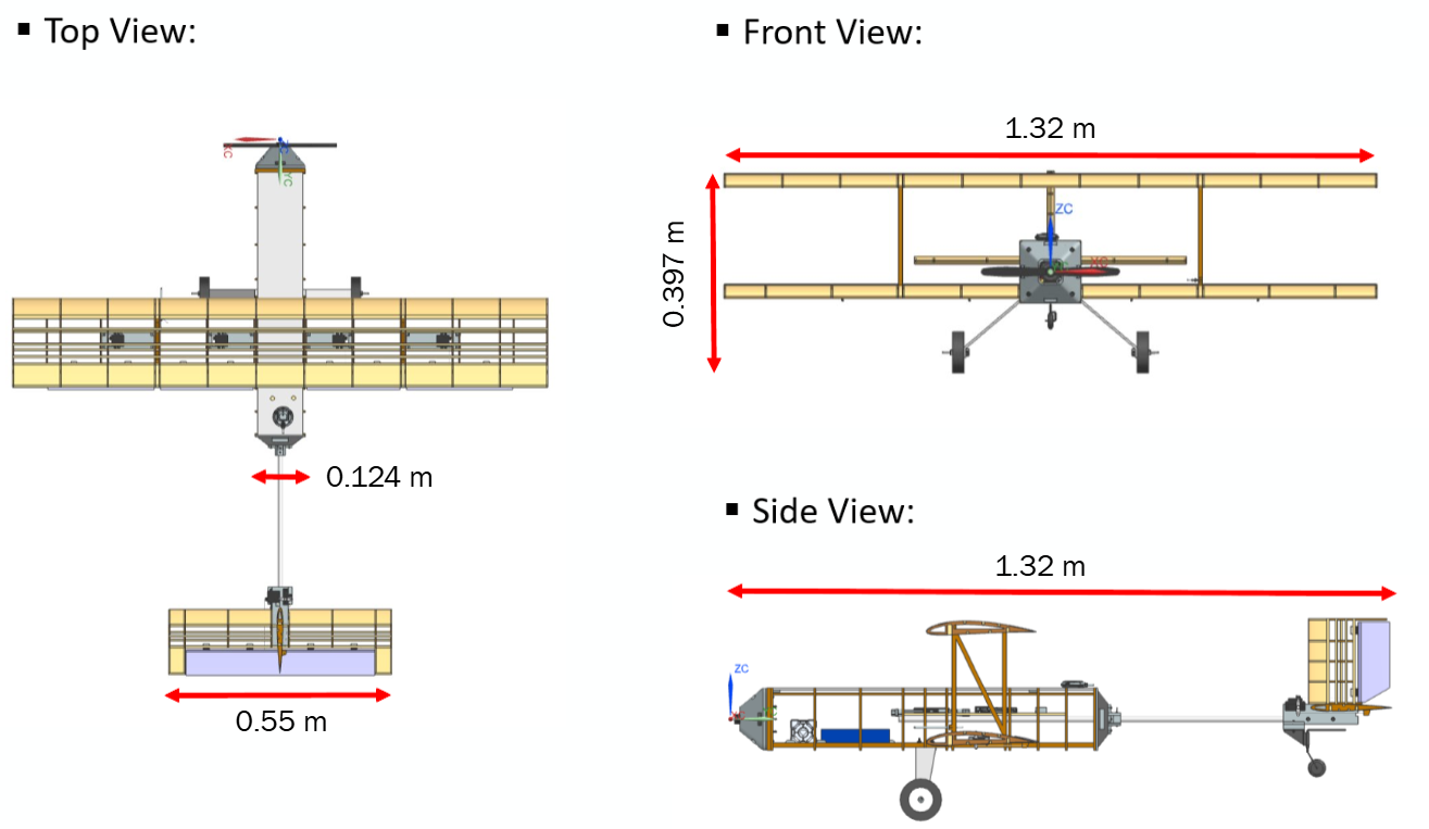
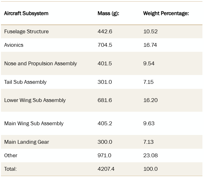
Summary of aircraft structure:
Fuselage analysis:
Avionics Placement
Avionics integration was designed to simplify wiring, maintain accessibility, and support proper center of gravity placement. All avionics were mounted on a dedicated balsa platform located in the central fuselage. The ESC and power module were positioned near the front to minimize battery and motor wire lengths, while the airspeed sensor was mounted adjacent to the pitot tube installation. The Pixhawk flight controller and associated adapter boards were positioned near the rear of the avionics tray to facilitate routing of servo wiring from the wings and tail. The GPS antenna was mounted on top of the fuselage to maximize satellite visibility and signal reception. This arrangement minimized wiring complexity while maintaining a clean and serviceable installation.
Final Design and Weight Estimate:
Final estimated weight buildup:
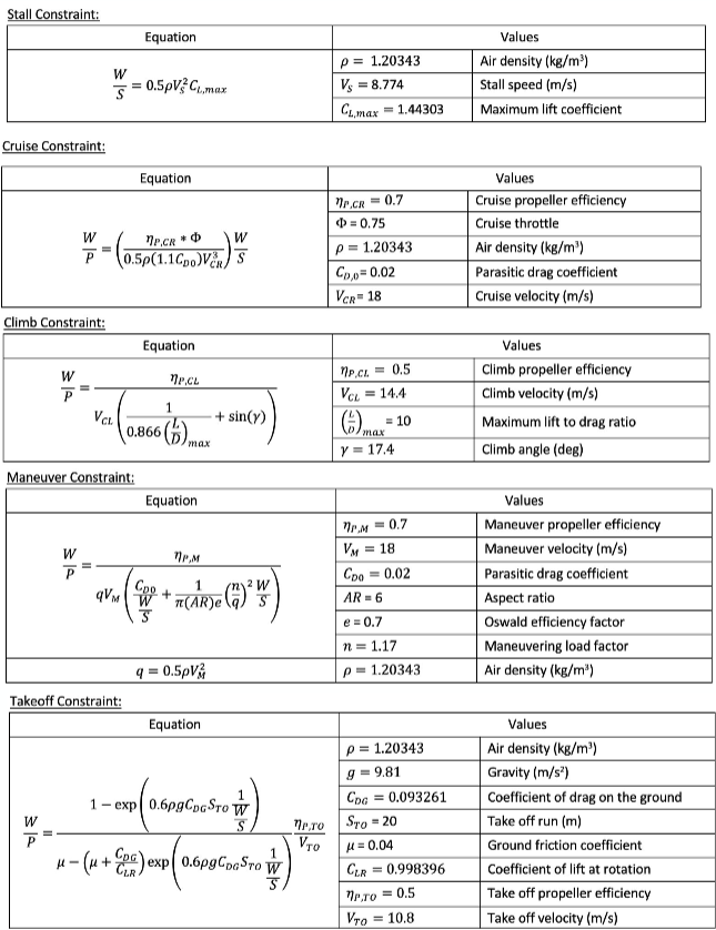
Constraint Equations
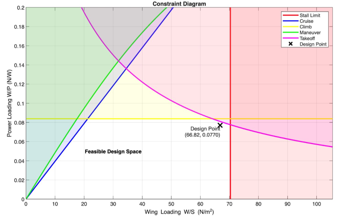
Constraint Diagram
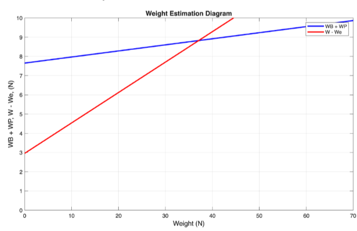
Weight Estimation Diagram
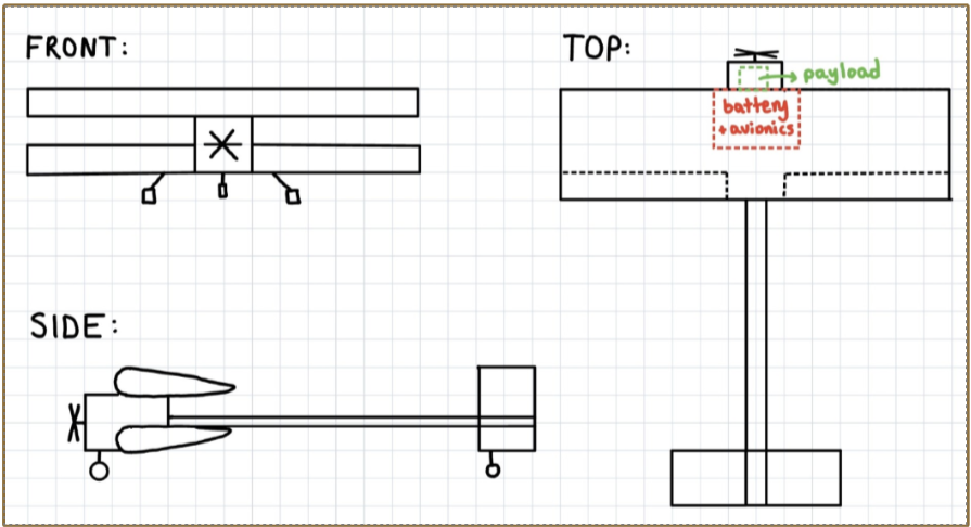
Chosen biplane design concept
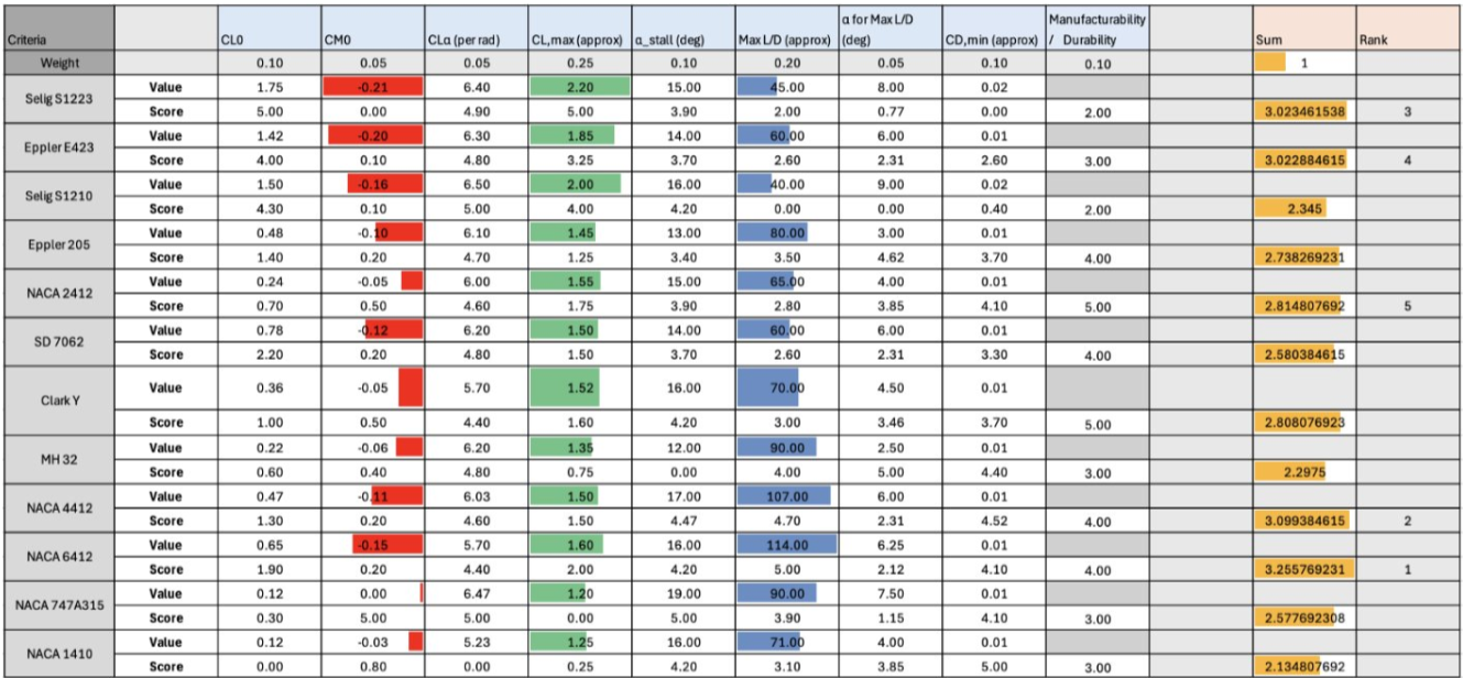
Main wing airfoil trade study
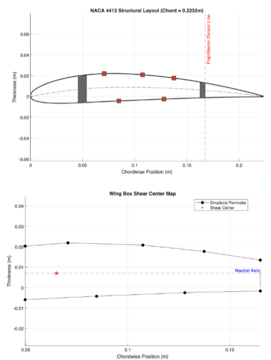
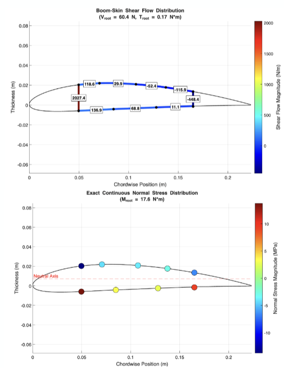
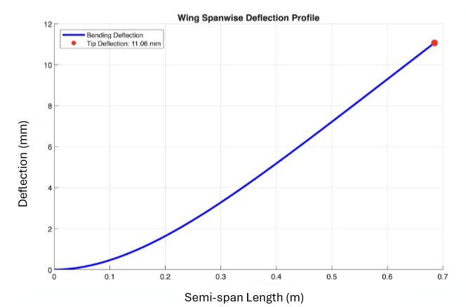
Wing box analysis:
V-n Diagram:
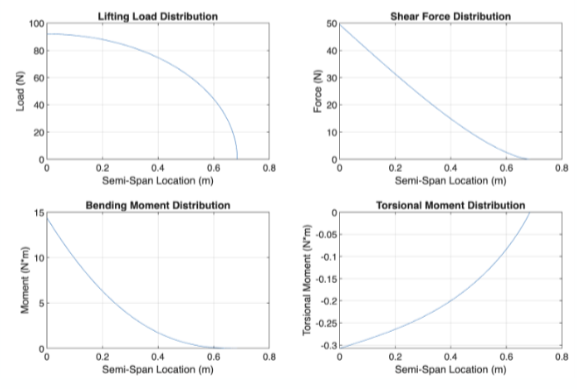
Upper wing load analysis:
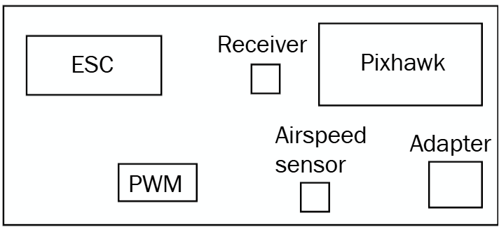
Sensor placement on avionics plate
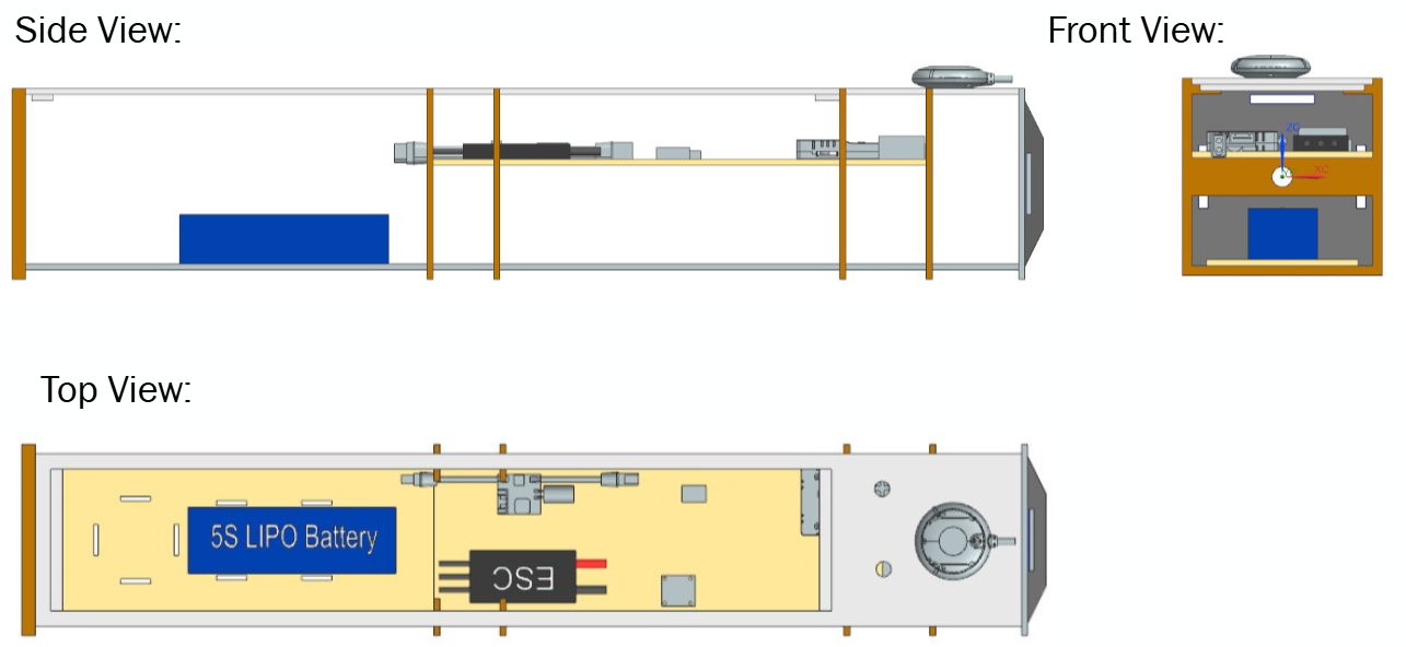
Avionics placement within the fuselage
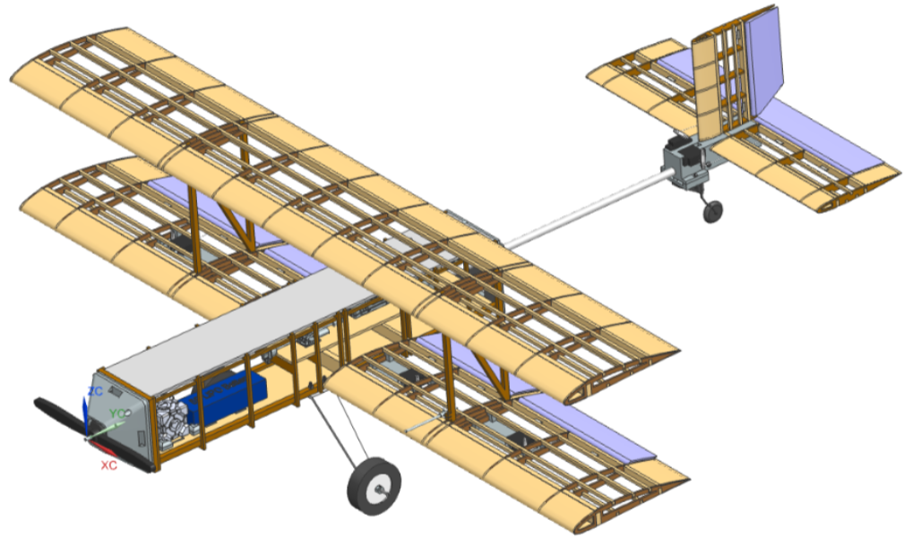
Final CAD:
Manufacturing and Assembly
Manufacturing of the aircraft relied heavily on digital fabrication methods to improve accuracy and repeatability. Laser cutting was used to produce numerous plywood components, including wing ribs, fuselage bulkheads, control horns, and structural frames. This process ensured dimensional consistency while significantly reducing fabrication time compared to manual methods. Additional structural components requiring greater thickness and strength, including spars, motor mounts, longerons, and wing connection members, were manufactured using a CNC wood router. The combination of laser cutting and CNC machining allowed rapid production of precise structural components while minimizing material waste.
The wing assemblies were constructed using laser-cut ribs mounted onto CNC-machined spars and reinforced with internal bracing. Careful attention was given to maintaining proper alignment and airfoil geometry during assembly. After structural completion, servo mounts were installed, and control surfaces were integrated into the wing structure. The horizontal and vertical tail assemblies followed a similar process, utilizing lightweight rib-and-spar construction optimized for aerodynamic loading conditions.
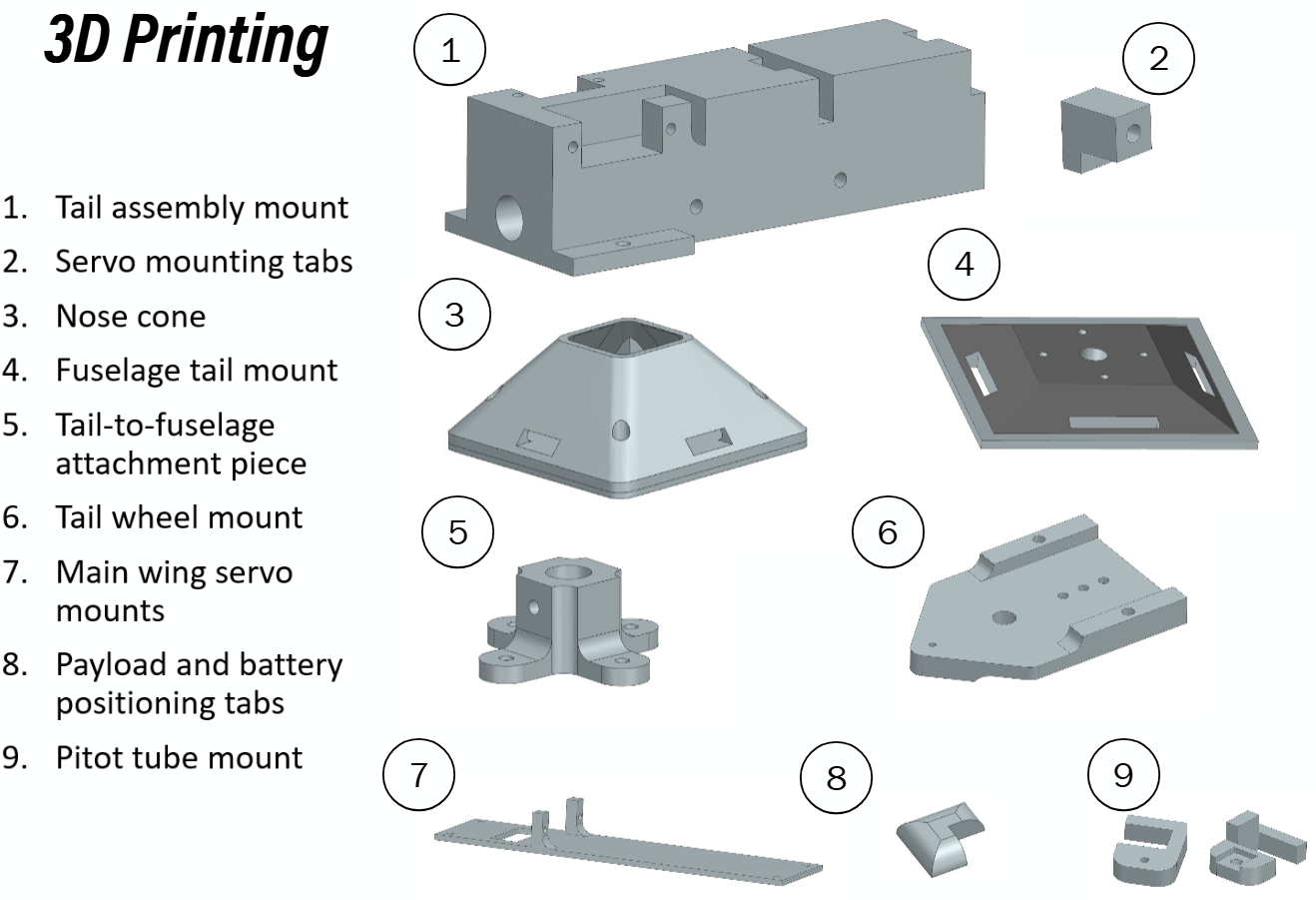
Fuselage assembly began with the alignment of plywood frames along the upper and lower longerons. Internal mounting points for the payload, avionics, battery, and propulsion system were integrated during construction to simplify final assembly. Numerous custom components were produced using additive manufacturing, including the nose cone, servo mounting tabs, tail wheel mount, pitot tube mount, battery positioning tabs, and wing attachment hardware. These 3D printed components enabled rapid customization and reduced manufacturing complexity for geometries that would have been difficult to fabricate using traditional methods.
Following structural assembly, the aircraft was covered using Monokote film to improve aerodynamic smoothness and provide environmental protection. The covering process required careful application to prevent warping of lightweight structures while maintaining proper tension across all flying surfaces. Final integration involved installation of avionics, propulsion components, control linkages, landing gear, and payload retention systems. Several integration challenges were encountered during assembly, including elevator and rudder mounting difficulties, fuselage frame alignment issues, and manufacturing-induced hole misalignments. These challenges required iterative modifications and highlighted the importance of accounting for manufacturing tolerances during the design phase.
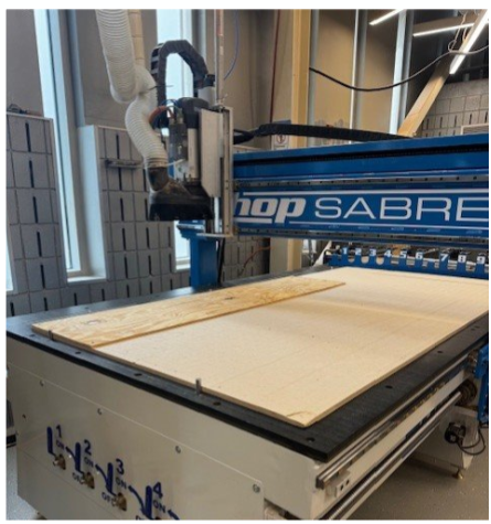
CNC wood router
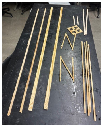
Plywood pieces cut out on the CNC wood router
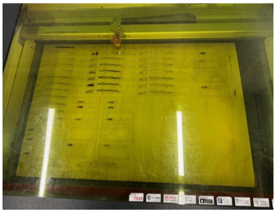
Laser cutting plywood sheet
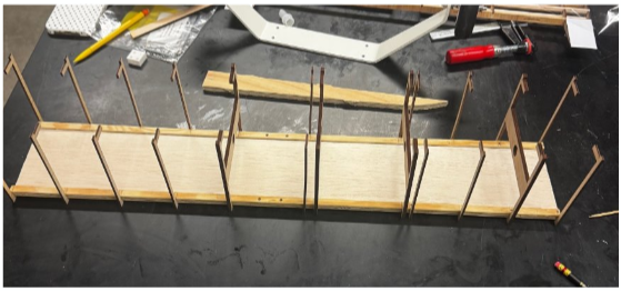
Fuselage assembly
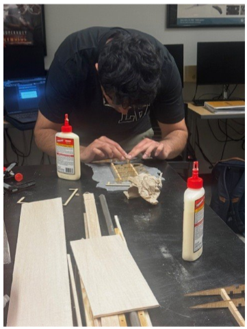
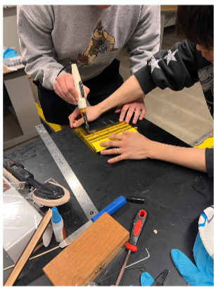
Applying wood glue to wing pieces
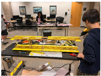
Monokoting wing assembly
Monokoting tail
Budget Considerations:
A significant challenge throughout the project was balancing performance objectives with the competition budget constraint of approximately $400. Design decisions continuously required tradeoffs between weight, strength, manufacturability, and component cost. The initial aircraft was completed for $376.18, successfully meeting the target budget. However, following the first flight-test accident, replacement materials and components were required for the rebuild, increasing the final project cost to $410.06. Despite slightly exceeding the original target after repairs, the team successfully maintained a highly capable aircraft while remaining close to the intended budget limit.
Flight Testing and Performance Analysis:
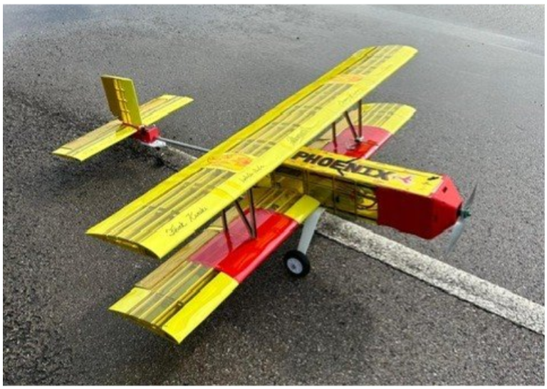
Flight testing provided valuable validation of the design methodology and aircraft performance predictions. During the initial flight attempt, the aircraft veered off the runway during takeoff and subsequently experienced a sharp corrective maneuver that resulted in an aerodynamic stall and crash. Investigation revealed that inadequate tail wheel rigidity contributed significantly to poor directional control during the takeoff roll. Following the accident, the aircraft was rebuilt with a redesigned tail wheel mounting system and modifications to payload placement that improved center of gravity positioning. These changes substantially improved takeoff stability and aircraft handling.
The rebuilt aircraft successfully completed flight testing and allowed comparison between predicted and measured performance. Analytical models predicted a takeoff distance of 16.9 m and a takeoff speed of 11.6 m/s, while measured values were 18.9 m and 10.4 m/s, respectively. The resulting errors of approximately 12% in distance and 10% in speed demonstrated good agreement between analysis and flight-test results. Post-flight evaluation identified several important lessons for future designs, including the importance of maintaining strict alignment between design and manufacturing, ensuring accurate tail incidence angles, improving taxi control through a steerable tail wheel, and performing more detailed pitch moment analyses. The project demonstrated the value of iterative engineering design and highlighted how careful testing, troubleshooting, and redesign can transform setbacks into successful engineering outcomes.
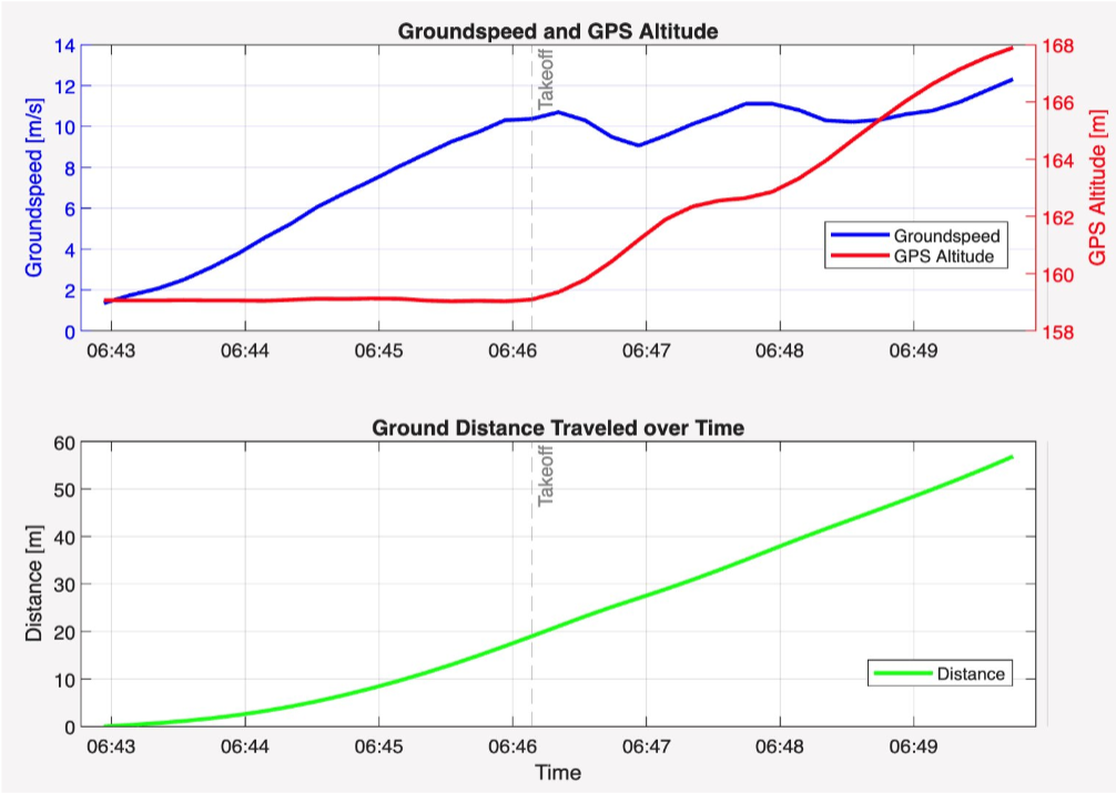
Takeoff validation plots
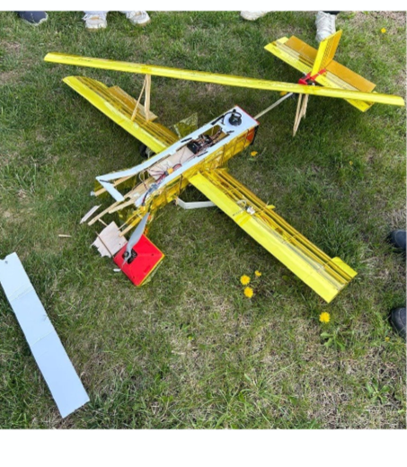
Airplane after the first flight test
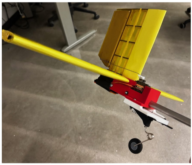
New tail wheel mount design